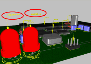
My lessons today is about NI Ultiboard. NI Ultiboard or formerly ULTIboard is an electronic Printed Circuit Board Layout program which is part of a suite of circuit design programs, along with NI Multisim. The NI Ultiboard interface enables efficient layout and routing of PCB designs. Integration with NI Multisim allows seamless transfer of schematics to layout. The customizable environment ensures accessibility to desired features for immediate productivity. Tools such as the spreadsheet view, toolbox and design wizards easily manage, control and define any board layout. Part placement and copper routes are optimized to either allow full control for precise definition of critical parts or automation for quick design completion. The 3D preview renders a completed, populated board to gain a virtual perspective before production. Ultiboard exports and produces industry standard format such as Gerber and DXF to take a final, optimized board to prototype and manufacture.
The Ultiboard product editions (Full, Power Pro) provide a complete set of tools for professional PCB layout:
- Intuitive, user-friendly design environment
- Integrated spreadsheet view for managing design constraints, part placement, and copper routing
- Easy-to-use design tools optimized for speed or precise control
- Export to industry standard file formats such as Gerber and DXF for prototype and manufacturing.
Ultiboard features intuitive tools for manual and automated part placement and routing. These tools combine to reduce the effort and time needed to complete repetitive tasks in PCB design. The flexble push-and-shove environment combined with placement processes ensure quick layout. Trace placement in Ultiboard offers flexibility to quickly and efficiently adjust based on the degree of design complexity. - Quickly find and place components with Pick-and-Place and Component Sequencer functionality
- Utilize the follow-me router and connection machine for immediate input and suggestion to any trace placement
- Access the speed and efficiency of the advanced Autoplace and Autoroute tools
- Use the autorouting functionality of former Electronics Workbench Ultiroute, which is now included in NI UltiboardSeamless integration with NI Multisim allows easy transfer of schematics to layout to quickly define a board for manufacture. Cross-probing ensures any landpattern can be selected at board level to simultaneously highlight the Multisim schematic counterpart. Forward and back annotation ensures that changes made at either the schematic or layout level are always reflected in both versions of a design. The overall integrated experience is paramount in providing an easy and quick flow from design and validation in Multisim to final prototype with Ultiboard.
- Easily transfer schematics to layout with seamless integration with NI Multisim
- Cross-probe NI Multisim schematics to immediately gain insight on how to design your PCB
- Forward and back annotate any changes made to the design


